How to Read the Brightness Level Using a Photoresistor
Name: Adam Aubry
NetID: aaubr
Description
- In this experiment we will use a photoresistor to detect the amount of light and then map that reading to a predefined level which will be displayed on the LCD.
These levels include:
- Dark
- Partially dark
- Medium
- Fully lit
- Brightly lit
Finally, we will display the number of milliseconds since the Arduino was last reset on the LCD’s second row.
Hardware:
- Arduino board
- Jumper wires
- Breadboard
- 10 WS2812B LED Strip
- 330 Ohm resistor
- 10 Ohm resistor
- 100 Ohm resistor
- 220 Ohm resistor
- 560 Ohm resistor
- 1k Ohm resistor
- 2k Ohm resistor
- 5k Ohm resistor
- 10k Ohm resistor
- Photoresistor
- 16x2 LCD PCF8574-type display
Additional functionality
A complementary feature will light up the WS2812 LED pixels so that the more light the photoresistor receives, the more LEDs will be lit. A similar effect occurs when less light is received — fewer LEDs will be lit.
Schematic
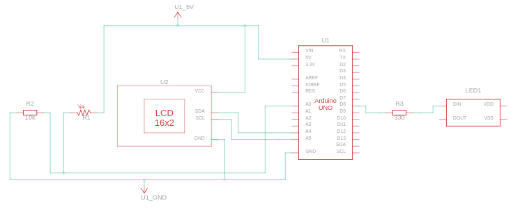
Steps
1. Wire the LCD 16x2
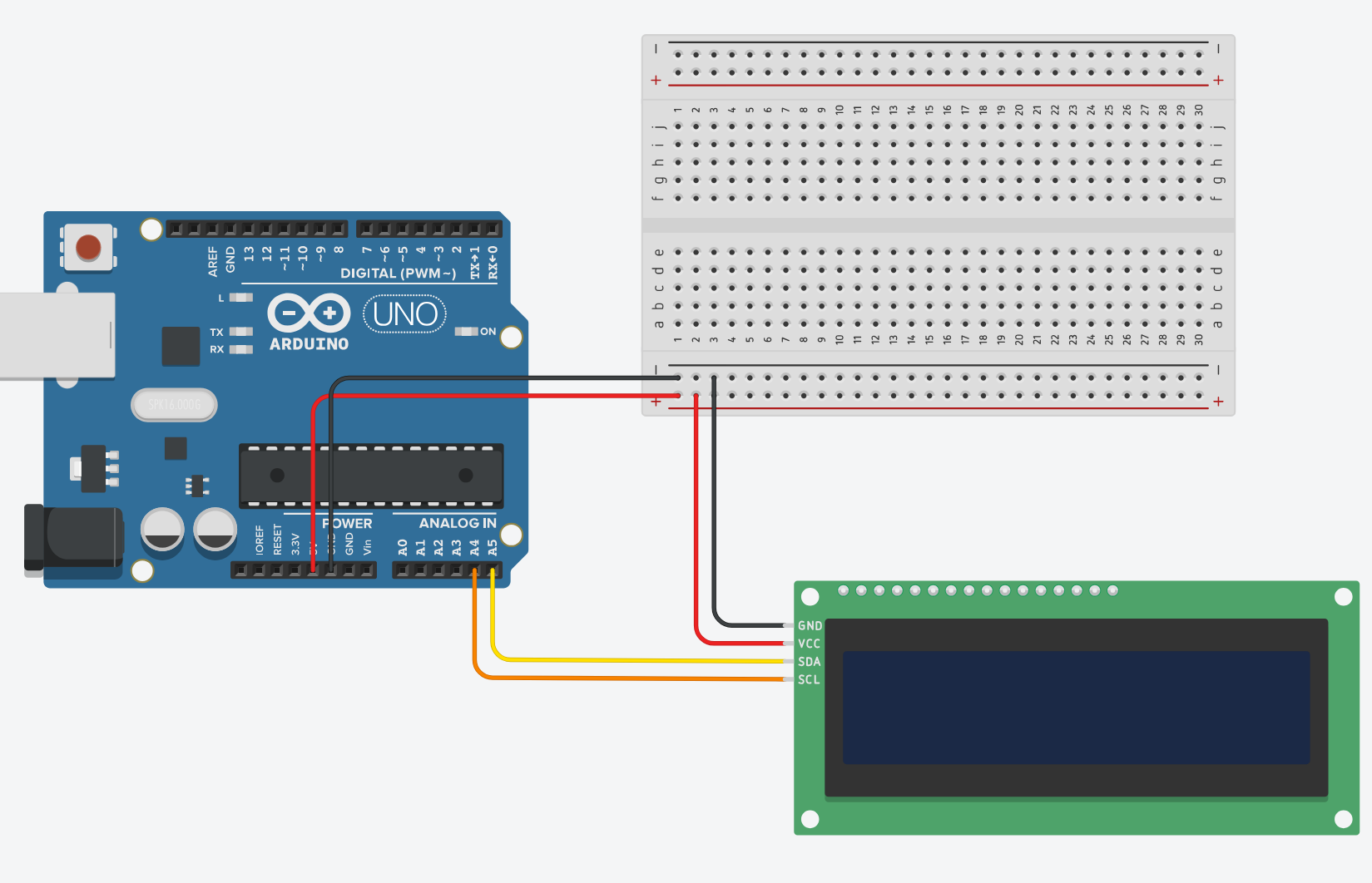
- SCL to A5
- SDA to A4
- VCC to 5v
- GND to Ground
2. Test the LCD connection to the Arduino
Let’s run a basic test to make sure the LCD is wired correctly and can communicate with the Arduino.
Since this module uses a PCF8574-based I/O expander, we’ll use the LiquidCrystal_I2C library.
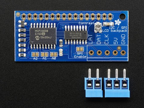
If your module uses the MCP23008 instead, use the Adafruit_LiquidCrystal library.
You can check the chip on the board for either PCF8574 or MCP23008 markings.
For example, here is what a MCP23008 board looks like:
For reference, a PCF8574 chip looks like this:
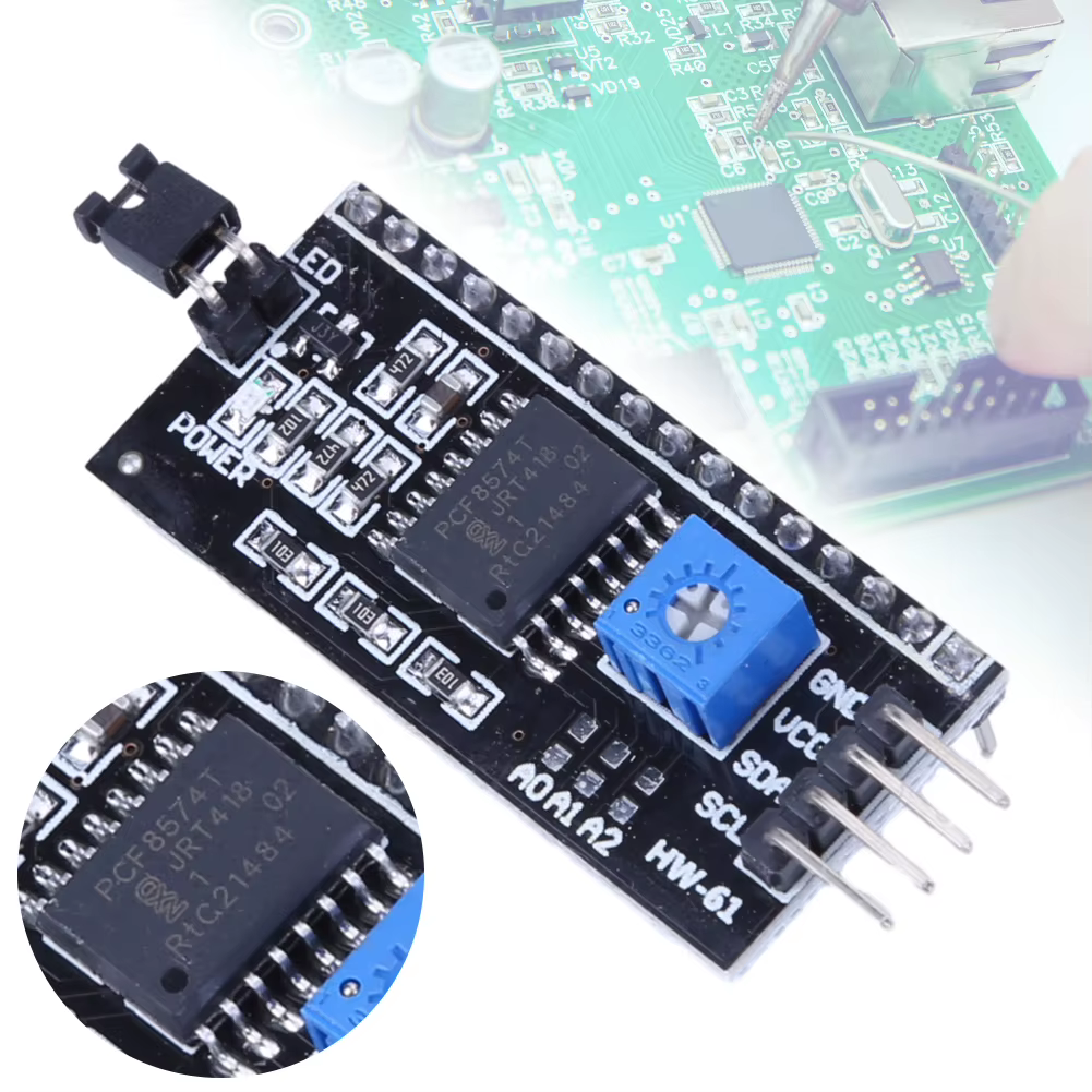
The difference between the chips is outside the scope of this lab. Knowing there are multiple translator chips when dealing with I2C LCDs is sufficient.
Next we’ll determine the I2C address of your LCD module. This address is
required when creating the lcd object in your main sketch.
Run the following code with the LCD connected as shown in the diagram above.
#include <Wire.h>

void setup() {
  // Initialize the I2C bus as a master device
  Wire.begin();
  Serial.begin(9600);
  while (!Serial); // Wait for Serial to connect
  Serial.println("\nI2C Scanner");
}

void loop() {
  byte error, address;
  int nDevices;

  Serial.println("Scanning...");
  nDevices = 0;
  // Test all addresses from 1 - 127
  for (address = 1; address < 127; address++) {
    // The i2c_scanner uses the return value of
    // Wire.endTransmission to see if a device is attached.
    Wire.beginTransmission(address);
    error = Wire.endTransmission();

    // error code 0 means a successful connection

    if (error == 0) {
      Serial.print("I2C device found at address 0x");
      if (address < 16)
        Serial.print("0");
      Serial.println(address, HEX);
      nDevices++;
    } else if (error == 4) {
      Serial.print("Unknown error at address 0x");
      if (address < 16)
        Serial.print("0");
      Serial.println(address, HEX);
    }
  }
  if (nDevices == 0)
    Serial.println("No I2C devices found\n");
  else
    Serial.println("Done\n");

  delay(5000); // Wait 5 seconds for next scan
}
This code will scan all possible I2C addresses (1-127) and report which addresses have devices connected. This tells you the specific address your LCD is using on the I2C bus, which you’ll need when creating the LCD object in your main program. Common LCD addresses are 0x27 or 0x3F.
Now let’s print a simple Hello World to test that we can
write text to the LCD.
#include <LiquidCrystal_I2C.h>

// Create lcd object with address found from program above
LiquidCrystal_I2C lcd(0x20, 16, 2);

void setup()
{
  // Initialize the LCD
  lcd.init();

  // Turn on the backlight
  lcd.backlight();

  // Print a message to the LCD.
  lcd.print("Hello World");
}

void loop()
{
}
The code creates the lcd object with the I2C address found by the scanner.
It initializes the LCD, turns on the backlight, and prints Hello World.
If you see Hello World on your display, the LCD is set up correctly.
3. Wiring the photoresistor
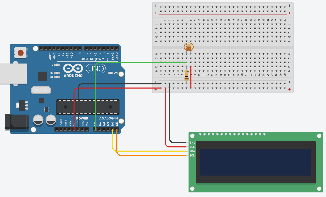
- One leg of the photoresistor to 5V
- The other leg to A0 and to a 10kΩ resistor to ground (resistor value may vary)
With this wiring the photoresistor will produce analog readings in the range 0–1023, where 0 is dark and 1023 is fully lit.
Let’s add two functions to the sketch. The first, setBrightness(), will be
called from loop() every 1000 milliseconds. It will call getBrightness() to read and map the photoresistor value. The initial mapping is shown here:
int brightnessLevel = map(lightRaw, 1023, 0, 10, 0);This maps the photoresistor’s readings (0–1023) into a smaller range (0–10). Printing the mapped value to the Serial Monitor helps determine which fixed resistor gives the best range for detecting different brightness levels.
#include <LiquidCrystal_I2C.h>

#define PHOTORESISTOR A0

// Create lcd object with address found from program above
LiquidCrystal_I2C lcd(0x20, 16, 2);

// Set up variables for non-blocking timing
unsigned long photoresistorReadingDelay = 1000;
unsigned long prevReadingMillis = 0;

unsigned long prevSerialPrint = 0;
unsigned long serialDelay = 1000;

void setup()
{
  // Initialize the LCD
  lcd.init();

  // Turn on the backlight
  lcd.backlight();
}

void loop()
{
  if ((millis() - prevReadingMillis) > photoresistorReadingDelay) {
    setBrightness();

    prevReadingMillis = millis();
  }
}

int getBrightnessLevel() {
  // Read the analog input from the photoresistor
  int lightRaw = analogRead(PHOTORESISTOR);
  // map the light values to a smaller range of values
  int brightnessLevel = map(lightRaw, 1023, 0, 10, 0);

  // Update serial with brightnessLevel
  if ((millis() - prevSerialPrint) >= serialDelay) {
    Serial.println(brightnessLevel);
    prevSerialPrint = serialDelay;
  }

}

void setBrightness() {
  int brightness = getBrightnessLevel();
}
4. Conducting the experiment
Now perform the experiment to determine which fixed resistor works best with the photoresistor.
Goal: A larger spread of values gives finer control over how the Arduino responds to changing light conditions.
The first column in the table is the resistor value; the second column shows the spread of analog values produced. For example, a 10Ω resistor yields readings between 0 and 1 across environments, while a 10kΩ resistor covers the full range.
| Resistor Value | spread of values by analog pin |
|---|---|
| 10 Ohm | 0-1 |
| 100 Ohm | 1-2 |
| 220 Ohm | 1-4 |
| 560 Ohm | 1-6 |
| 1k Ohm | 1-8 |
| 2k Ohm | 1-8 |
| 5k Ohm | 1-9 |
| 10k Ohm | 1-10 |
Here is how I categorized different brightness levels:
| Environment | Example setup |
|---|---|
| Brightly lit | HappyLight (a very bright lamp) |
| Fully lit | HappyLight placed further away |
| Medium | Normal room lighting |
| Partially dark | Cover the photoresistor with your hand but allow some light |
| Dark | Fully cover the photoresistor and turn lights off |
Now that we have a suitable range, we map it into five intervals to match the
environments. Dividing 10 by 5 yields intervals of size 2. This final mapping is
used to decide which value getBrightness() should return.
// Return the brightness level that maps to
// 5 values to represent the five different brightness types
if (brightnessLevel >= 8) return 1;
else if (brightnessLevel >= 6) return 2;
else if (brightnessLevel >= 4) return 3;
else if (brightnessLevel >= 2) return 4;
else return 5;
5. Finishing the LED lighting
The value returned from getBrightness() is used in a switch statement. Each
case corresponds to a different brightness level and updates the LCD and LEDs.
The updateLEDs() calls are commented out until the LED code is added.
The updateDisplayText() function simply takes the brightness label and
displays it on the LCD.
Here is all the code that we have so far.
#include <LiquidCrystal_I2C.h>

#define PHOTORESISTOR A0

// Create lcd object with address found from program above
LiquidCrystal_I2C lcd(0x20, 16, 2);

// Set up variables for non-blocking timing
unsigned long photoresistorReadingDelay = 1000;
unsigned long prevReadingMillis = 0;

unsigned long prevSerialPrint = 0;
unsigned long serialDelay = 1000;

void setup()
{
  // Initialize the LCD
  lcd.init();

  // Turn on the backlight
  lcd.backlight();
}

void loop()
{
  if ((millis() - prevReadingMillis) > photoresistorReadingDelay) {
    setBrightness();

    prevReadingMillis = millis();
  }
}

int getBrightnessLevel() {
  // Read the analog input from the photoresistor
  int lightRaw = analogRead(PHOTORESISTOR);
  // map the light values to a smaller range of values
  int brightnessLevel = map(lightRaw, 1023, 0, 10, 0);

  // Update serial with brightnessLevel
  if ((millis() - prevSerialPrint) >= serialDelay) {
    Serial.println(brightnessLevel);
    prevSerialPrint = serialDelay;
  }

  // Return the brightness level that maps to
  // 5 values to represent the five different brightness types
  if (brightnessLevel >= 8) return 1;
  else if (brightnessLevel >= 6) return 2;
  else if (brightnessLevel >= 4) return 3;
  else if (brightnessLevel >= 2) return 4;
  else return 5;
}

void setBrightness() {
  int brightness = getBrightnessLevel();

  // Set the LCD's brightness and update the
  // strip of LEDs with the correct amount of pixels and light
  // to display.
  switch (brightness) {
      case 1:
          updateDisplayText("brightly lit");
          // updateLEDs(10, 255);
          break;
      case 2:
          updateDisplayText("fully lit");
          // updateLEDs(8, 150);
          break;
      case 3:
          updateDisplayText("medium");
          // updateLEDs(6, 128);
          break;
      case 4:
          updateDisplayText("partially dark");
          // updateLEDs(4, 64);
          break;
      case 5:
          updateDisplayText("dark");
          // updateLEDs(2, 32);
          break;
      default:
          updateDisplayText("Not detected");
          // updateLEDs(0, 0);
          break;
  }
}

void updateDisplayText(char* brightness) {
  lcd.clear();

  // update display with brightness level text on row 1
  lcd.setCursor(0, 0);
  lcd.print(brightness);
}
When you run the code, it should report the current brightness level on the LCD.
- Adding the time to the second row on the LCD
Displaying the time since the Arduino was last reset (in milliseconds) is
straightforward — call the built-in millis() function and print the value on
the LCD’s second row. Here is the updated code:
#include <LiquidCrystal_I2C.h>

#define PHOTORESISTOR A0

// Create lcd object with address found from program above
LiquidCrystal_I2C lcd(0x20, 16, 2);

// Set up variables for non-blocking timing
unsigned long photoresistorReadingDelay = 1000;
unsigned long prevReadingMillis = 0;

unsigned long prevSerialPrint = 0;
unsigned long serialDelay = 1000;

void setup()
{
  // Initialize the LCD
  lcd.init();

  // Turn on the backlight
  lcd.backlight();
}

void loop()
{
  if ((millis() - prevReadingMillis) > photoresistorReadingDelay) {
    setBrightness();

    prevReadingMillis = millis();
  }
}

int getBrightnessLevel() {
  // Read the analog input from the photoresistor
  int lightRaw = analogRead(PHOTORESISTOR);
  // map the light values to a smaller range of values
  int brightnessLevel = map(lightRaw, 1023, 0, 10, 0);

  // Update serial with brightnessLevel
  if ((millis() - prevSerialPrint) >= serialDelay) {
    Serial.println(brightnessLevel);
    prevSerialPrint = serialDelay;
  }

  // Return the brightness level that maps to
  // 5 values to represent the five different brightness types
  if (brightnessLevel >= 8) return 1;
  else if (brightnessLevel >= 6) return 2;
  else if (brightnessLevel >= 4) return 3;
  else if (brightnessLevel >= 2) return 4;
  else return 5;
}

void setBrightness() {
  int brightness = getBrightnessLevel();

  // Set the LCD's brightness and update the
  // strip of LEDs with the correct amount of pixels and light
  // to display.
  switch (brightness) {
      case 1:
          updateDisplayText("brightly lit");
          // updateLEDs(10, 255);
          break;
      case 2:
          updateDisplayText("fully lit");
          // updateLEDs(8, 150);
          break;
      case 3:
          updateDisplayText("medium");
          // updateLEDs(6, 128);
          break;
      case 4:
          updateDisplayText("partially dark");
          // updateLEDs(4, 64);
          break;
      case 5:
          updateDisplayText("dark");
          // updateLEDs(2, 32);
          break;
      default:
          updateDisplayText("Not detected");
          // updateLEDs(0, 0);
          break;
  }
}

void updateDisplayText(char* brightness) {
  lcd.clear();

  // update display with brightness level text on row 1
  lcd.setCursor(0, 0);
  lcd.print(brightness);

  // Set the time in milliseconds for row 2
  lcd.setCursor(0, 1);
  lcd.print(millis());
}- Adding a strip of 10 LED pixels to the system
Next, add a strip of 10 addressable LEDs to the system. The number of lit pixels will follow the five brightness intervals. For example, a brightly lit environment (mapped to a value >= 8) will light up 10 pixels.
Here is the wire diagram.
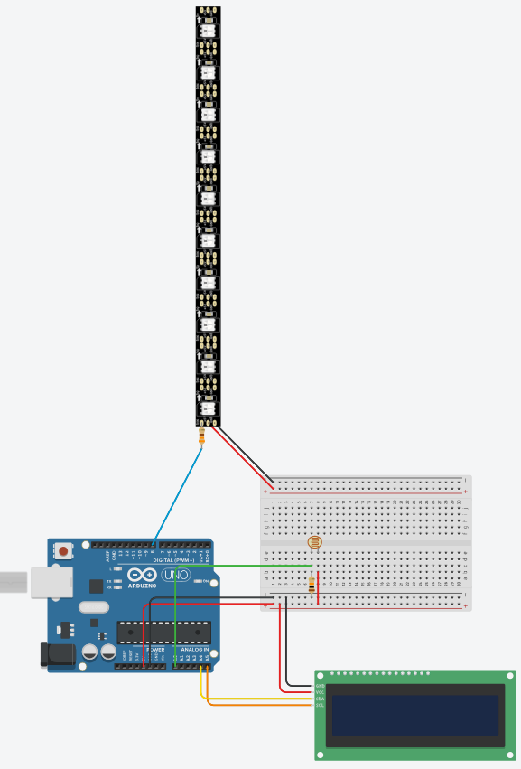
- Data line goes to 330 ohm resistor and then to pin 8
- Ground goes to ground
- Power goes to 5v power
I used WS2812B LEDs; this guide was helpful in understanding how to control them.
The guide mentions the FastLED library. Install it from the Arduino Library Manager (search for “FastLED” by Daniel Garcia) and include it in your sketch. Here is the final code that integrates the LED strip.
#include <LiquidCrystal_I2C.h>

#define PHOTORESISTOR A0

// Create lcd object with address found from program above
LiquidCrystal_I2C lcd(0x20, 16, 2);

// Set up variables for non-blocking timing
unsigned long photoresistorReadingDelay = 1000;
unsigned long prevReadingMillis = 0;

unsigned long prevSerialPrint = 0;
unsigned long serialDelay = 1000;

// pin for LED strip
const int LED_PIN = 13;
const int NUM_LEDS = 10;
int lastNumLEDs = 0;

// define array of type CRGB .
// CRGB type contains three 1-byte data member
// for Red, Green, and Blue color channels
CRGB leds[NUM_LEDS];

void setup()
{
  // Initialize the LCD
  lcd.init();

  // Turn on the backlight
  lcd.backlight();
}

void loop()
{
  if ((millis() - prevReadingMillis) > photoresistorReadingDelay) {
    setBrightness();

    prevReadingMillis = millis();
  }
}

int getBrightnessLevel() {
  // Read the analog input from the photoresistor
  int lightRaw = analogRead(PHOTORESISTOR);
  // map the light values to a smaller range of values
  int brightnessLevel = map(lightRaw, 1023, 0, 10, 0);

  // Update serial with brightnessLevel
  if ((millis() - prevSerialPrint) >= serialDelay) {
    Serial.println(brightnessLevel);
    prevSerialPrint = serialDelay;
  }

  // Return the brightness level that maps to
  // 5 values to represent the five different brightness types
  if (brightnessLevel >= 8) return 1;
  else if (brightnessLevel >= 6) return 2;
  else if (brightnessLevel >= 4) return 3;
  else if (brightnessLevel >= 2) return 4;
  else return 5;
}

void setBrightness() {
  int brightness = getBrightnessLevel();

  // Set the LCD's brightness and update the
  // strip of LEDs with the correct amount of pixels and light
  // to display.
  switch (brightness) {
      case 1:
          updateDisplayText("brightly lit");
          updateLEDs(10, 255);
          break;
      case 2:
          updateDisplayText("fully lit");
          updateLEDs(8, 150);
          break;
      case 3:
          updateDisplayText("medium");
          updateLEDs(6, 128);
          break;
      case 4:
          updateDisplayText("partially dark");
          updateLEDs(4, 64);
          break;
      case 5:
          updateDisplayText("dark");
          updateLEDs(2, 32);
          break;
      default:
          updateDisplayText("Not detected");
          updateLEDs(0, 0);
          break;
  }
}

void updateDisplayText(char* brightness) {
  lcd.clear();

  // update display with brightness level text on row 1
  lcd.setCursor(0, 0);
  lcd.print(brightness);

  // Set the time in milliseconds for row 2
  lcd.setCursor(0, 1);
  lcd.print(millis());
}

void updateLEDs(int brightnessLevel, int brightnessVal) {

  // don't update if photoresistor hasen't detected a brightnessLevel change
  if (lastNumLEDs == brightnessLevel) {
    return;
  }

  // Clear current level displayed
  for (int i = 0; i < lastNumLEDs; i++) {
    leds[i] = CRGB(0, 0, 0);
  }

  for (int i = 0; i < brightnessLevel; i++) {
    leds[i] = CRGB(brightnessVal, 0, 0);
  }

  FastLED.show();

  lastNumLEDs = brightnessLevel;
}
Conclusion
The lights should now reflect the amount of light present in your environment while also indicating this as text on your LCD display. Overall this project is a great way to learn how to combine different components together to create a fully functioning system.